
Bipolar junction transistors also known as BJTs are made from semiconductors like silicon and germanium. They are basically use for switching and amplification. BJTs are three terminals solid state components that use only two carriers to conduct electricity namely holes and electrons, this account for their name "bipolar" meaning two current carriers (holes and electrons). BJTs are made from the direct combination of two different semiconductors to form a three terminal device.
Types of BJTs.
There are two types of bipolar junction transistors namely NPN junction and PNP junctions.
1. PNP Junction transistor

This type of transistor is fabricated from junction of different semiconductor materials. An N-TYPE semiconductor is sandwiched between two P-TYPE semiconductors, thus forming three layers with three terminals. Mostly all PNP transistors are made from silicon due to the ease of manufacturing and abundance (it's the most abundant material on earth after oxygen). It circuit symbol is usually identified with an arrow at the emitter pointing in. This means current flows from the emitter to the collector when in the ON mode.

Working principle of a PNP transistor
PNP transistors consists of three terminals namely emitter, base and collector. The emitter to base connection is like a forward biased diode while the base to collector connection is like a a reverse biased diode.
An PNP transistor is just like two diodes connected back to back in opposite direction. When the emitter is connected to a power source with the positive polarity of a battery connected to the emitter and the negative polarity connected to the base, current flows from the emitter to the base because of excess holes and low depletion mode.
The transistor is in the off state when the base voltage is 0v , therefore no current flows from the emitter to the collector, however if the base voltage increased slightly by connecting a resistor to it, large current flows from the emitter to the collector, thus the transistor is in the on state.
PNP transistors do have different configuration of their base, emitter and collector, they can exit in the following forms.
- common emitter.
- common base
- common collector.
Circuit applications of PNP.
1.As a switch.
A PNP transistor acts as a switch in either fully on or fully off. When their is no base current or the base is disconnected from the ground (-) of a power source it functions as an open switch, whereas if a little current of at least 0.75V flows through the base it triggers current to flow from the emitter to collector therefore acting as a fully ON switch.

Application of PNP as a switch in circuits.
• As a switch.
In this circuit we're going to demonstrate how PNP transistors are used in circuits to trigger a load e.g an LED, depending on some conditions like when there's light or when it's dark. This circuit can be use to trigger up something when there is light e.g putting on a switch and switching it off when it senses darkness.

When the LDR (Light Dependent Resistor) is exposed to enough light it resistance decreases from it infinite resistance (i.e blocking current totally) when placed in darkness to zero. This makes current to flow through the base thus triggering current to flow from the emitter then to the collector then to the LED. In this phase it acts as a switch and causes the LED to lit up. But when the LDR is blocked from receiving light, this makes no current to flow through the base and this makes the PNP to behave as an open switch thus the LED won't lit up.
•As an amplifier.

A PNP transistor works as an amplifier by amplifing a weak signal V+EE at the emitter to base junction and cause a large current to flow at the collector.
Common PNP transistors.
Below are lists of common PNP transistors used in circuits with their pinouts.
•BD136

•A1015

•BC558

•2N6107

•TIP32C

•BC857

•KSA1220

• 2SA1943

•2N3906

•BC557

2. NPN transistors.
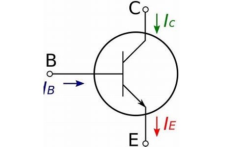
Symbol of an NPN transistors.
NPN transistors are fabricated by sandwiching a P-TYPE semiconductor between two N-TYPE semiconductors thus forming a three terminals solid state component. It consists of three terminals namely emitter, base and collector. Current flows from collector to the emitter that's why it is usually represented in circuits with an arrow at the emitter pointing out. Majority of the carriers in an NPN transistor are electrons while the least are holes.
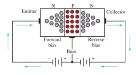
Working principles of an NPN transistors
An NPN transistor looks like two diodes connected together in series in opposite direction with the emitter to base in forward bias and the base to collector in reverse bias. When an NPN transistor is connected to a DC power supply by connecting the negative polarity to it emitter and the positive terminal to the base, current flows from the collector to emitter and functions as an on switch. The transistor functions as either fully on or off depending on the magnitude of the current that flows through it base. If a resistor is attached to the base, that the current flowing through it is below 0.75v it acts like an insulator thus current doesn't flow through it.
Circuit applications of an NPN Transistors.
• As a current controlled switch.
NPN transistors function as a switch just like PNPs, the only difference between them is the way they are connected. Both function as a current controlled switch, in which little current at the base triggers a large amount of DC to flow through it. The circuit below shows how NPNs are connected in circuits as a switch.

As shown in the schematic diagram above, the emitter is connected to the negative terminal of a cell and the base connected to the positive terminal of the cell with a switch and a resistor in series. An LED is connected in forward bias with a resistor in series with the collector and the positive terminal of the cell. When the switch is left open, the LED won't lit up because no current flows from the collector to the emitter. As soon as the switch is on, current flows through the circuit and makes the LED lit. In practical circuits the switch is replaced with sensors to trigger a load when it senses a change. For example a temperature controlled air conditioner circuits have the circuit above with the switch replaced with a NTC thermistor. When a room reached to a certain temperature the NTC allows current to flow through it and triggers the transistor to power on a Fan.
• As an amplifier.
An NPN transistor functions as an amplifier by using a low signal or current at the base to emitter junction to control a large flow of current at the collector to emitter junction.

As shown in the circuit above, when a low current is applied to the base and emitter of the transistor, this trigger a large current to flow from the collector(c) to the emitter.
Common NPN transistors.
Here are common NPN transistors and their pinouts.
•BD139
•BC549
•2N5306.
•2N5088
•2N4401
•SSB050
•SL100
•T1P31
•BC548
•2N551
•TIP122
•MPSA42
•2N2222
•2N3904
•BC547
Tags:
Power Electronics