Bread board or solderless board is a temporary board use for prototyping and testing circuit before soldering on PCBs or vero boards.
It made up of metal contacts which are use to form rows. To connect an electronic component to the bread board you just have to plugin the component let say a resistor into the holes.
For beginners like you the solderless board is one of the tools you have to be familiar with. You will use it to test circuits, learn about how electronic components can be connected together to form a simple or compled circuit. In this article you are going to learn about the bread board, how it works, how to use it and at the end of this tutorial you should be able to use the board to make simple circuits like powering an LED with a battery.
How the bread board/solderless board is connected.
The bread board is made up rows and columns. Roles are connected to one another while the column are also connected to another. The rows at the end of the bread board is usually use to draw in current from a power supply like battery or AC mains or draw out current. This rows are called the power bar.
All other rows of metals are connected together.

In the diagram above, the blue lines are connected to one another, it is use for connecting (-) current into the board, while the red line are all connected together. It is use for connecting (+) power source into the board.
All other rows in the board have each of their holes connected together. They are use for connecting components like ICs, capacitors, diodes, resistors and all other electronic components.
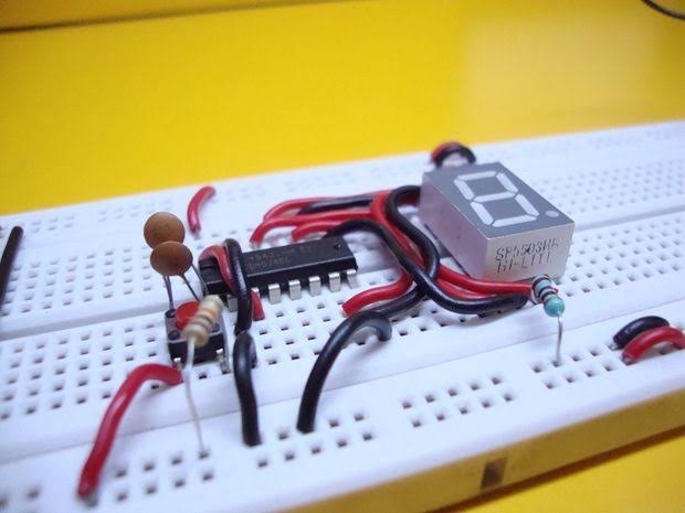
Activity: connecting simple components on the bread board.
Now that we have known about how the bread board is connected, let's get started with building a simple circuit on the bread board.
What you will need.
1. Resistor
2. LED
3. Battery connector
4.9v battery
5. Connecting wires.
Steps: